UART in the STM32 features a halfduplex mode, enabled by setting UART_CR3.HDSEL. When enabled, the UART stops listening on the UART_Rx pin (as assigned in GPIO matrix). Instead, it connects its internal Rx node to the Tx node, and stops actively driving the UART_Tx pin unless transmission is in progress. This is a rarely used feature, so here are some remarks about its usage:
-
Halfduplex mode enables to connect several microcontrollers using a single signal wire. There's no enforcement of which participant transmits when: transmitter does not check its own receiver and starts transmitting immediately after its data register is written. So, measures have to be taken to prevent pin damage in case of two transmitters pushing against each other.
RM in description of this mode in the UART chapter requires to set the Tx pin to Open Drain mode with pullup, which is a foolproof method but also limits baudrate (due to RC constant of pullup and parasitics). Another option is to use series resistors to limit current - Ohm's law and datasheet-given constraints apply (and again, the resulting RC constant limits achievable baudrate). Chosen solution also implies level of immunity against induced noise.
-
In case of such multi-drop bus, it may be a good idea to implement in software some form of scheduling (usually a master-slaves scheme, but others exist too; RS485 users are familiar with this concept).
-
Receiver listens to transmission (i.e. it "sees the echo"), so software has to be written with this in mind.
-
"Direction" (i.e. whether output transistors are enabled or not) of UART_Tx pin, when halfduplex is enabled, is controlled by the UART module. It is automatically turned to input whenever the UART module is not transmitting. The UART_Tx pin has to be set as Alternate Function (with appropriate AF number). This works in the same way also in the GPIO-atypical 'F1 family.
-
When not transmitting, the input pin is floating and potentially drifting to zero, which results in missing the first startbit and thus data corruption. It is reasonable to use a pullup to define idle level.
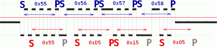
In figure below, to demonstrate idle level (i.e. periods when transmitter is not active), UART_Tx pin was pulled by a voltage divider to middle point between GND and VDD; and sequence of 0x55-0x56-0x57-0x58 was transmitted. Would idle level drift to ground, it would be equivalent of the receiver's decision level being at the red line - receiver would see a continuous 0 until the end of the first startbit, so it would see the second bit as startbit. Receiver would receive corrupted data, with Framing errors at first, third and fourth byte.
-
The newer UART version (since 'F0/'F3) features the UART_DE signal to control transceivers (e.g. for RS485) during transmission. This signal is an identical copy of the internal signal which controls the GPIO pin's "directionality". In this version of UART, it is possible to generate an actively driven idle period before (and after) transmission using the USART_CR1.DEAT (.DEDT), up to almost 2-bit-long period.
This is illustrated in the figure below, with the same setup as for the previous figure. The top waveform was taken with USART_CR1.DEAT = 0; the middle waveform with USART_CR1.DEAT = 0x1F while the bottom waveform is the UART_DE signal for the latter.

-
UART_Tx pin in halfduplex mode is not driven during the IDLE frame (generated as consequence of setting UART_CR1.TE), exactly as the UART_DE signal.
-
In case of pin placement pressure and if Rx-only UARTs are needed and the UART_Rx pin is unavailable (used for a different purpose), using halfduplex may be a neat trick to use the UART_Tx pin for Rx.
-
Another neat trick to spare one pin is to use halfduplex mode in conjunction with the similarly naturally halfduplex RS485 bus.